How to Prevent Air Leaks in Vacuum Lift Tubing in 2026?

Time:2026-10-05 Author:Ethan
0%

How to prevent air leaks in vacuum lift tubing? In 2026, this question matters more than ever. Vacuum lifters depend on stable suction, clean fittings, and tubing that withstands repeated movement. A tiny leak can reduce lifting force, increase pump workload, and create an unsafe load release.

John F. O’Hanlon, author of A User’s Guide to Vacuum Technology, is widely associated with the practical warning, “A vacuum system is only as good as its weakest seal.” That principle applies directly to vacuum lift tubing. Inspect hose ends for flattened walls, cuts, stiffness, and whitening near bends. Check every connector by hand. Loose clamps often feel secure but leak under vibration. They need controlled tightening, not excessive force.

Begin with a visual inspection. Then isolate the tubing and measure pressure decay with a calibrated gauge. For difficult faults, trained technicians may use helium leak detection. Do not rely only on listening for hissing. Small leaks can remain silent. Apply an approved leak-detection fluid around joints, but keep contamination away from porous components and filters. Replace damaged tubing instead of masking it with tape. That shortcut rarely survives repeated lifting cycles.

Temperature changes, oil residue, and sharp bends deserve attention. So does operator handling. A perfect installation can still fail through careless dragging. I have seen maintenance teams overlook one hardened elbow while replacing an entire hose assembly. That was inefficient. It was also preventable. A documented inspection schedule, clear replacement limits, and a final load test provide stronger evidence than appearance alone. Reliable vacuum performance begins with disciplined details.
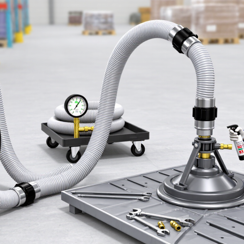
How to Prevent Air Leaks in Vacuum Lift Tubing in 2026?

Understanding Common Causes of Air Leaks in Vacuum Lift Tubing

Air leaks in vacuum lift tubing often begin at small connection points, not in the middle of the hose. Loose clamps, hardened seals, and poorly seated fittings allow air to enter during lifting. A hose may look intact while its inner wall has collapsed or cracked. Small leaks matter. I have seen operators replace a pump when the real fault was a damaged tube near the connector.

Abrasion is another common cause. Tubing rubbing against a frame can develop thin spots, especially around bends and moving joints. Heat, cleaning chemicals, oil, and sunlight may also weaken the material. Check the hose after heavy use, then flex it gently near each fitting. Listen for a faint hiss. A drop in lifting force can provide another warning. Do not guess. Isolate the section and test it.

Reliable maintenance requires a repeatable inspection routine. Confirm that clamps are tight but not cutting into the tube. Examine seals for flattening, dirt, or distortion. A simple vacuum decay test can reveal leaks that sound checks miss. Mark recurring damage points, because repeated failure may indicate poor routing or excessive bending. I sometimes focus too much on visible cracks; invisible seal damage is easier to overlook. Rechecking after installation is worth the extra minutes. A clean joint should hold stable vacuum during a controlled lift.

How to Prevent Air Leaks in Vacuum Lift Tubing in 2026?

Understanding common causes of air leaks helps maintenance teams inspect the highest-risk areas first. The chart uses a practical inspection-priority score from 0 to 10, based on the typical severity and frequency of common tubing failure modes.

Key takeaway: Start with tubing damage, loose connections, and worn seals. Preventive inspections should include visual checks, fitting-tightness tests, seal replacement, and leak testing after maintenance.

Inspecting Tubing, Fittings, Seals, and Connection Points

Vacuum lift tubing can lose performance through small, overlooked air leaks. In 2026, routine inspection remains one of the most effective preventive measures. Run your fingers along the tubing while the system operates. Feel for soft spots, unusual vibration, or escaping air. Listen closely. A faint hiss often appears before a visible defect.

Inspect fittings at both ends, especially threaded adapters and quick connections. Confirm that each fitting sits squarely and does not rotate under light hand pressure. Over-tightening can deform plastic threads or damage sealing surfaces.

Use the correct seal for the material, temperature, and vacuum level. A seal may look intact but still flatten permanently after repeated use. Replace hardened, cracked, or swollen seals immediately.

Connection points deserve extra attention. Dust, oil, and tiny fibers can prevent complete contact between tubing and fittings. Clean them with a lint-free cloth before assembly.

Then test the system under normal working conditions, not only at idle. A pressure-drop test can reveal gradual leakage that a short visual check misses.

I once blamed the tubing for weak lifting force. The real problem was a slightly loose fitting. That assumption was wrong.

Keep inspection records with dates, symptoms, and replaced parts. These notes help technicians identify recurring failures, although records are not always complete in busy workshops.

Flexible tubing should also avoid sharp bends and rubbing against metal edges. Small abrasion marks can become serious leaks later.

Selecting Compatible Tubing and Sealing Components

Preventing air leaks in vacuum lift tubing begins with selecting components that work as one system. Measure the tube’s inner diameter, wall thickness, and required bend radius before ordering parts. A tube that fits loosely around a connector may seal briefly, then leak when the equipment vibrates. Check the tubing’s vacuum rating, temperature range, and resistance to oils or cleaning fluids. Flexible tubing should bend smoothly, not flatten near the lifting handle or connection point.

Sealing components deserve equal attention. Choose O-rings that match the vacuum level, temperature, and chemicals used in the workplace. Inspect each sealing surface for scratches, dust, or tiny cuts. Even a small particle can create a slow pressure loss. Use fittings designed for the tubing material, and avoid forcing mismatched sizes together. Hand-tightening is often safer than excessive force, which can deform a seal or crack a fitting.

Test the assembled line before daily operation. Isolate the tubing, apply vacuum, and watch the gauge for pressure decay over several minutes. A flexible section that slowly contracts may indicate weak tubing or a poor connection. Do not rely only on visual inspection. It misses small leaks. A common mistake is replacing the tube without checking the seal seat, clamp alignment, or connector surface. That approach feels efficient, but it can repeat the same failure. Record the tested configuration, because memory is less reliable than a simple maintenance note.

Installing and Securing Vacuum Lift Tubing Correctly

Installing and securing vacuum lift tubing correctly prevents many air leaks before testing begins. Use tubing with the correct inside diameter, wall thickness, and vacuum rating. The U.S. Department of Energy reports that compressed-air leaks can waste 20–30% of compressor output. Vacuum systems differ, but the energy lesson remains relevant: small leaks create continuous pump demand.

Cut each tube squarely with a sharp cutter. A slanted cut can damage the seal inside a push-fit connector. Insert the tube fully, then pull it gently to confirm engagement. Avoid tight bends near fittings. Use a bend radius recommended by the tubing manufacturer, and support long runs with smooth clamps rather than sharp cable ties. Over-tightening is common. It can deform the tube and create a hidden leak.

ISO 4414 emphasizes safe pneumatic system design, while EN 13155 addresses safety for lifting attachments. These standards support secure connections, controlled loads, and regular inspection. In practice, I would test every joint with a vacuum gauge and a compatible leak-detection solution. A stable reading matters more than a quick pass. Recheck after the tubing warms, moves, or carries a load. My earlier mistake was trusting visual inspection alone. It missed a tiny split beside a clamp. A pressure-loss log, dated inspection labels, and documented replacement intervals provide stronger evidence of control.

Testing, Monitoring, and Maintaining Leak-Free Performance

In 2026, leak prevention starts with repeatable testing, not a quick glance at the vacuum gauge. For venturi-powered lifting equipment, the U.S. Department of Energy reports that compressed-air leaks commonly waste 20–30% of compressor output. Its guidance also identifies below 5% as a practical leak-management target. This is not a vacuum-tubing failure rate, but it shows why small leaks deserve measurement. Inspect tube bends, end fittings, seals, and pickup pads while the system is isolated. Look for flattened tubing. Use a calibrated gauge.

Measure vacuum decay from a known starting point, then repeat after ten minutes under identical conditions. Record temperature, load, tube length, and valve position. Otherwise, comparisons become misleading. ISO 4414 supports documented pneumatic-system risk controls, while ISO 10012 emphasizes controlled measurement processes. Install a local vacuum switch or digital sensor where operators can see trends. Set alarms from the verified machine baseline, not a convenient guess. Sudden drift often reveals a loose connector before the load visibly drops. Alarms can fail. No checklist catches every failure.

Tips: Apply approved leak-detection fluid to accessible joints; bubbles identify escaping air, but clean residue afterward. Never bend tubing sharply beside a fitting. Replace hardened seals during scheduled service, and tag every repair with its date, test result, and technician. The DOE recommends repairing leaks promptly and verifying savings. That final retest is often skipped. It should not be.

How to Prevent Air Leaks in Vacuum Lift Tubing in 2026? - Testing, Monitoring, and Maintaining Leak-Free Performance

The values below are practical reference targets for vacuum lift tubing and connections. Always confirm final limits against the lift manufacturer's design, rated load, hose material, and applicable workplace-safety requirements.

Control Area What to Check Recommended Method Reference Frequency Acceptance Criterion Corrective Action
Pre-use inspection Tube surface, end fittings, clamps, seals, and quick connectors Visual inspection combined with gentle manual movement of each connection Before every shift or lifting cycle No cuts, abrasion, kinks, swelling, loose fittings, cracked seals, or visible deformation Remove damaged tubing from service; reseat or replace the affected seal, fitting, clamp, or tube
Vacuum level Operating vacuum at the lift circuit or vacuum pad manifold Read the installed vacuum gauge or calibrated electronic vacuum sensor while the system is isolated Before use and during operation Must remain within the equipment's specified operating range; many industrial lifting systems operate approximately between -60 and -80 kPa gauge, depending on design Stop lifting if the vacuum cannot reach or hold the specified level; inspect tubing, valves, filters, and seals
Pressure-decay leak test Leakage in tubing, fittings, manifolds, and isolated vacuum circuits Evacuate the isolated circuit, close the isolation valve, record the starting pressure, and measure pressure recovery for a fixed period Commissioning, after repair, and at least monthly for critical lifting equipment Pressure change remains below the site's documented limit during the test period; use the same test volume, temperature, and duration for trend comparison Repeat the test to confirm the result, then isolate sections progressively to locate the leaking component
Vacuum decay rate Rate at which vacuum is lost after the pump or generator is isolated Log vacuum level at regular intervals, such as every 10 or 30 seconds, using a calibrated gauge or data logger During scheduled preventive maintenance Stable or improving trend with no sudden increase in decay rate; compare readings with the equipment baseline Investigate any sudden change, especially after hose movement, connector replacement, impact, or exposure to heat and chemicals
Bubble testing Accessible joints, threaded fittings, hose ends, and valve connections Apply an approved leak-detection solution to a pressurized section or use a suitable method specified for the equipment When a pressure-decay test indicates leakage No continuous bubble formation at the joint Depressurize safely, tighten only to the fitting specification, replace damaged seals, and retest
Tracer-gas testing Small or concealed leaks that cannot be located by visual or bubble testing Use a qualified tracer-gas leak-test procedure with a calibrated detector; ISO 20485 provides general guidance for tracer-gas leak testing After repeated unexplained vacuum loss or during major overhaul Leak rate is below the documented safety and performance limit for the lifting system Mark the leak location, repair or replace the component, evacuate the circuit, and repeat the test
Tubing flexibility Hardening, brittleness, flattening, permanent kinks, and loss of elasticity Inspect the tube along its complete routed length and check bend areas during normal movement Weekly, or more often in high-cycle applications Tube maintains its designed inside diameter and returns to shape without cracking or collapsing Replace tubing that has become brittle, permanently flattened, kinked, or chemically damaged
Bend radius Routing around frames, moving joints, and cable carriers Compare the installed bend with the tubing supplier's minimum static and dynamic bend-radius requirements During installation and after routing changes Bends remain above the specified minimum radius with no sharp folding or twisting Reroute the tube, add suitable strain relief, or install a longer section to prevent tension and over-bending
Connection security Push-to-connect fittings, barbed fittings, clamps, threaded joints, and locking rings Check alignment, insertion depth, locking engagement, and fitting torque where applicable Before use and after any maintenance activity Connections are fully seated, mechanically secured, and free from rotation or side loading Cut tubing squarely, reinsert to the required depth, replace damaged fitting components, or use the correct clamp
Vacuum filter condition Clogging, moisture, dust loading, and filter-housing seal condition Inspect the filter element and compare the pressure or vacuum reading before and after the filter Weekly; replace according to contamination level and maintenance records No excessive pressure drop, moisture carryover, or damaged housing seal Drain, clean, or replace the filter element and renew the housing seal if required
Temperature exposure Heat from machinery, sunlight, hot surfaces, and cold-weather embrittlement Inspect hose routing and compare service temperature with the tubing material specification At installation and during seasonal inspections Operating temperature remains within the tubing and seal manufacturer's rated range Install heat shielding, reroute the tube, or replace it with a compatible material rated for the environment
Chemical compatibility Contact with oils, solvents, cleaning agents, coolants, and ultraviolet exposure Review the chemical exposure history and inspect for swelling, discoloration, softening, or surface cracking Monthly and after chemical exposure No material change that affects flexibility, wall thickness, or sealing performance Identify the contaminant, clean using an approved method, and replace incompatible tubing or seals
Dynamic movement test Leakage that occurs only when the lift arm, hose reel, or vacuum head moves Operate the equipment through its normal range while monitoring vacuum level and observing hose movement After installation changes and during quarterly maintenance Vacuum remains within the specified operating range throughout the complete movement cycle Remove torsion and tension, improve support, replace fatigued tubing, and repeat the movement test
Alarm and monitoring system Low-vacuum alarm, visual indicator, audible warning, and sensor response Use the approved functional-test procedure to simulate a low-vacuum condition without lifting a load Daily functional check and documented monthly verification Alarm activates at the equipment's specified threshold and remains clearly visible or audible Take the equipment out of service until the sensor, alarm, wiring, or power supply is repaired and retested
Load-holding verification Ability of the complete vacuum circuit to maintain a safe load condition Perform only the manufacturer's approved no-load or controlled test procedure; never use an unapproved test load After repairs and at the interval required by the site's safety program The system maintains the specified vacuum and passes all required safety checks without abnormal decay Quarantine the lift, investigate the complete circuit, and document the repair before returning it to service
Maintenance records Test date, vacuum readings, decay results, replaced parts, and technician identification Use a digital or paper maintenance log with consistent test conditions Every inspection and repair Complete, traceable records with baseline readings and documented corrective actions Establish a baseline after commissioning and review trends for gradual deterioration or recurring failures
Replacement planning Age, cycle count, environmental exposure, and recurring leak history Base replacement on condition and risk rather than appearance alone Review at least annually or according to the risk assessment Replacement interval is defined in the preventive-maintenance plan and updated when inspection data changes Replace tubing proactively when repeated repairs, material degradation, or unexplained vacuum loss indicates reduced reliability

FAQS

Where do air leaks in vacuum lift tubing usually begin?

They often start at clamps, seals, fittings, or connectors. The hose center may look perfect. Small gaps can still reduce lifting force.

How can I detect a small leak during operation?

Listen for a faint hiss and feel along the tubing. Check for soft spots, vibration, or escaping air. A vacuum decay test can reveal quieter leaks.

What signs show that a seal needs replacement?

Replace seals that are hardened, cracked, swollen, flattened, or distorted. Dirt and oil can also prevent proper contact. A seal may look usable but fail under vacuum.

How should fittings and connection points be checked?

Confirm each fitting sits squarely and does not rotate with light hand pressure. Clean dust and fibers with a lint-free cloth. Check both ends of every tube.

What installation mistakes commonly create hidden leaks?

Slanted cuts, incomplete insertion, tight bends, and excessive clamp pressure are common mistakes. Cut tubing squarely and pull it gently after insertion. I once trusted appearance alone. That was not enough.

How can tubing damage develop during regular use?

Rubbing against metal frames creates thin spots near bends and moving joints. Heat, oil, chemicals, and sunlight can weaken the material. Flex the tube gently near each fitting.

What testing method gives more reliable results than visual inspection?

Test each joint with a vacuum gauge and a compatible leak-detection solution. Use normal operating conditions, not only idle testing. Recheck after warming, movement, and lifting.

How can recurring tubing failures be prevented?

Record inspection dates, symptoms, damaged locations, and replaced parts. Mark repeated failure points on the tubing or routing plan. Records may be incomplete in busy workshops. Review them anyway.

Conclusion

How to prevent air leaks in vacuum lift tubing? Start by understanding the most common causes, including worn tubing, loose fittings, damaged seals, cracks, contamination, and poorly aligned connections. A careful inspection should cover the entire vacuum path, especially connection points, bends, clamps, and sealing surfaces. Identifying small defects early can prevent reduced lifting performance, unstable vacuum pressure, and unnecessary equipment downtime.

Choose tubing, fittings, and sealing components that are compatible with the system’s vacuum level, operating environment, temperature, and load requirements. During installation, cut tubing cleanly, insert it fully, avoid sharp bends, and secure every connection without over-tightening. After assembly, test the system for pressure loss and listen or observe for signs of leakage. Regular monitoring, cleaning, and replacement of aging components will help maintain reliable, leak-free performance and extend the service life of the vacuum lift system.

Ethan

Ethan

Ethan is a seasoned marketing professional with a deep expertise in our company's innovative product line. With a passion for sharing knowledge and insights, he takes the lead in regularly updating our corporate blog, where he explores industry trends, product features, and effective marketing......